Growing potatoes requires a lot of time and effort. During the season, potato bushes need to be tucked several times: cover the stems with loose earth to provide the roots with free air access and retain moisture. Thanks to hilling, lateral shoots (stolons) develop better, more new tubers are formed.
The use of small-scale mechanization equipment greatly facilitates this process. There are many types of attachments for walk-behind tractors or mini-tractors, as well as various hand tools designed for hilling.
Types of hillers
The easiest way is to loosen the soil in the aisles with a hoe or hoe and pour soil under the bushes, forming mounds. But it is much more convenient to form ridges with a manual potato hiller. By hanging such a device on a walk-behind tractor or an electric cultivator, you can quickly process even fairly large areas.
In one pass, a manual hiller is processed on one side of two adjacent rows, and if the working element is attached to the walk-behind tractor, then several at once. In a small area it is more convenient to use a hand tool.
In specialized stores, a variety of models of hillers are sold, each of them has its own principle of operation. When choosing a tool for yourself, you need to take into account the size of the area to be processed, and if there is a walk-behind tractor or other unit – the brand and characteristics.
Depending on the principle of work, hillers are:
According to the device of the working element, the hillers are classified as follows:
- models with a constant working width (distance between discs or plowshares);
- models with adjustable working width.
Fig. 1 and Fig. 2 show manual hillers. These models are usually equipped with one working element and comfortable handles (for two people to work together).
Fig 1. Disc hiller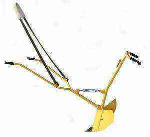 Fig 2. Plow with adjustable angle of attack
Fig. 3 shows a mounted disc device with a connecting unit to a moto-cultivator or mini-tractor. Such hillers can have one or several pairs of discs (or several plows) mounted on a special beam. The number of working elements depends on the power of the machine.
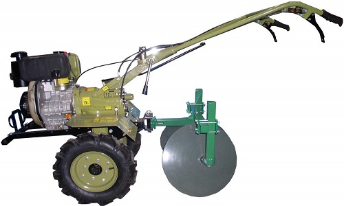 Fig 3. Motoblock with disc hiller and adjustable working width
Independent production of hillers
Buying such equipment is not cheap. Having skills in plumbing and the necessary tools, you can save money by making a potato hiller from scrap materials.
Let us consider in more detail the design features of the hillers, which can be made independently.
The most popular among gardeners are disc models, the main element of which is a pair of concave metal discs installed at an angle relative to each other. In turn, hillers of this type can be with a fixed or adjustable distance between the discs and the angle of inclination relative to the vertical stand. The discs are mounted directly on the axle or with plain bearings, which greatly facilitates the work.
Hillers with plows (lister) are considered the simplest, and therefore the most reliable in work. They come with a constant distance between the shares or with installed spacers, with which you can change the width of the capture (photo, Fig. 4). This type of hillers has a disadvantage – they require a cultivator of more power than disc cultivators.
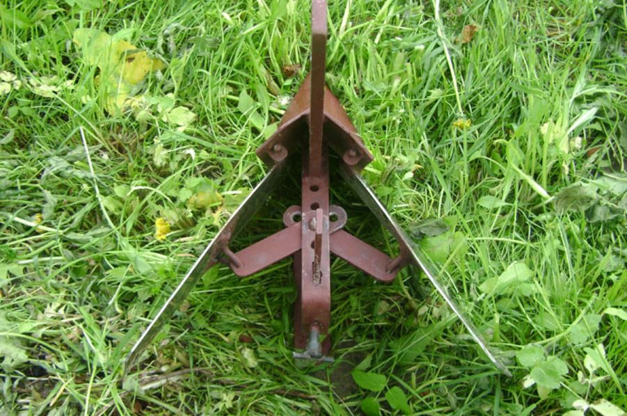 Fig. 4. Plow with adjustable working width
Making a manual disc-type hiller
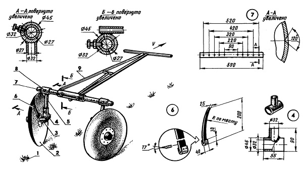 Fig. 5. Assembly diagram of a manual disc hiller
Getting started, you first need to make a drawing of a disk-type hiller, guided by the detailed assembly diagram and putting down the exact dimensions.
To make such a device, you will need the following tools:
- gas cutter – for cutting sheet metal parts and steel profiles;
- gas welding station – for joining parts with welded seams;
- gas burner – for heating areas of metal parts before bending them;
- vice and other locksmith tools;
- a powerful drill and a set of carbide drills for metal;
- angle grinder (grinder) – for cleaning welded seams;
- pipe bender – desirable, but not required.
Manual disc hiller assembly diagram
Land with potato sprouts; 2. Disks – 2 pcs .; 3. Cam-type mechanism – 2 pcs .; 4. Bracket – 2 pcs .; 5. Stand – 2 pcs .; 6. Scraper – 2 pcs .; 7. Bridge beam – 1 piece; 8. Locking bolt – 2 pcs .; 9. Handle-beam – 1 pc.
The bridge girder is made of a pipe 32 mm in diameter with a wall thickness of at least 2,5 mm.
Stand (pos. 5 fig. 5)
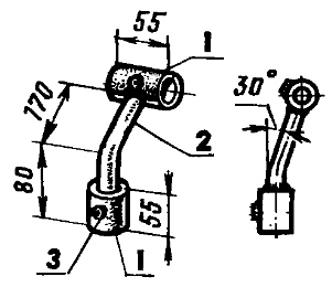 Fig. 6. Rack for disc hiller
Bushing – 2 pcs. Thick-walled steel pipe with a diameter of 45 mm (45×6,5);
Jumper – 1 pc. Steel pipe with a diameter of 32 mm (32×2,5):
Nut М10 – 2 pcs.
Handle-beam (pos. 9 fig. 5)
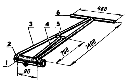 Fig. 7. Handle-beam
Sleeve – 1 pc. (steel pipe 45 × 6,5, 120 mm long);
Nut Ml0 – 2 pcs.;
Communication – 2 pcs. (steel pipe 21 × 2,5, 1400 mm long);
Ukosin – 1 pc. (Steel pipe 21 × 2,5, 700 mm long);
Crossbar – 1 pc. (steel pipe 21 × 2,5);
Handle – 1 pc. (steel pipe 21 × 2,5, 450 mm long).
Scheme for adjusting the working width of the disc hiller
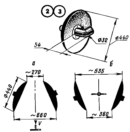 Fig. 8. Scheme for adjusting the working width of the disc hiller
View a – collapse; view b – convergence
Description of the assembly process
The main structural element is two concave metal discs connected to each other with a diameter of 370 to 700 mm with sharpened edges. They must be made of steel sheet with a thickness of at least 2 mm. Craftsmen solve this problem in different ways, someone even adapts the lids from large pots that have failed. Others cut off the bottom and top of the old boiler’s heating tank, or the discs can be removed from the old planter. Old large diameter saw blades can be used. But the best thing, of course, is to make stainless steel discs and shape them in production.
The simplest option is to fasten the discs using bushings welded to each other (two pipe sections 25 mm in diameter and 50–80 mm long). In this case, the distances between the lower points and the angles of inclination of the discs always remain unchanged. The discs rotate due to the sliding of the axles in the bushings filled with grease (for the axles, bolts of a suitable diameter and length are selected). With a similar design, the row spacing will have to be made equal to this distance.
If hubs are welded to the discs, each of which will have two plain bearings (203, single-row ball bearings are suitable), and the axes of the discs are combined with the struts using homemade cam mechanisms, then the discs will be able to rotate freely, which will greatly facilitate the work. A steel scraper mounted on the axle on the concave side of each disc will scrape away adhering soil during operation.
Several through holes are drilled on the bridge beam with a pitch of 50 mm in order to adjust the distance between the discs to the size of the row spacing. You can work with such a mechanism alone, but it is easier and more convenient – together. It is advisable to make front and rear rods. Then one person will push the device from behind, and a partner will guide and pull it forward.
In fig. 6, 7, 8 respectively show how the vertical posts are arranged and how the handle-beam looks like. In fig. 8 – disc mounting and ways of adjusting them.
Installing a homemade hiller on a walk-behind tractor
The hiller installed on the walk-behind tractor must be equipped with a clutch unit with the unit. It must be made, taking into account the connecting dimensions of the counterpart, and provide pins that will firmly connect the attachment to the unit. All parts of the clutch assembly must be made of a sheet of high-carbon steel with a thickness of at least 5-7 mm. Bolts of suitable diameter and length can be used as pins.
Diagram of a disc hiller intended for installation on a mechanical or electric cultivator
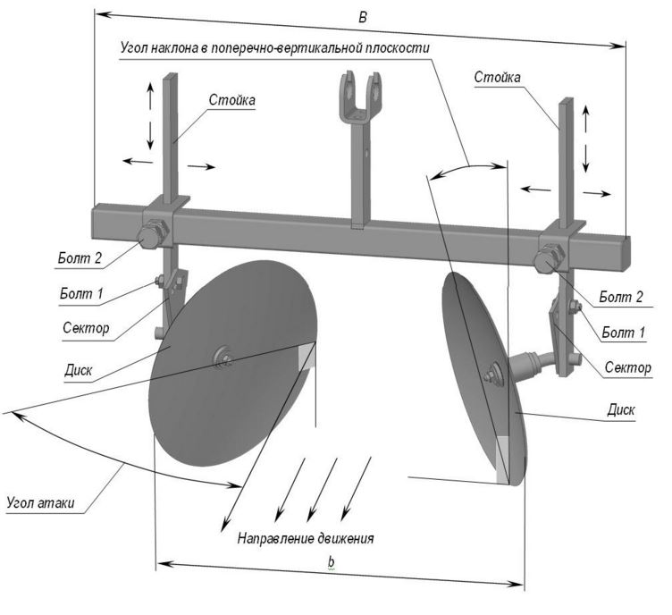 Fig. 9. Diagram of a disc hiller for installation on a mechanical cultivator
In order to be able to adjust the angle of rotation of the disks, two lanyards are installed on the beam (see Fig. 10). To change the distance between the discs, a series of bolt holes are drilled in the beam. The design must be completely symmetrical, otherwise during operation it will be difficult to withstand movement in a straight line, the hiller will begin to move to the side.
In fig. 10 shows the location of turnbuckles and special bolts (B and C), with the help of which the position of the discs is adjusted.
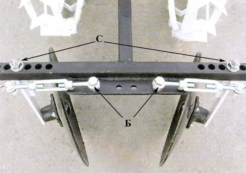 Fig. 10. Adjustment with lanyards
Making a plow hiller
It is also possible to make a lister (plow) type potato hiller with fixed “wings” and with an adjustable distance between them.
Drawing of a plow for a hiller with an adjustable width between plowshares, recommended for self-production.
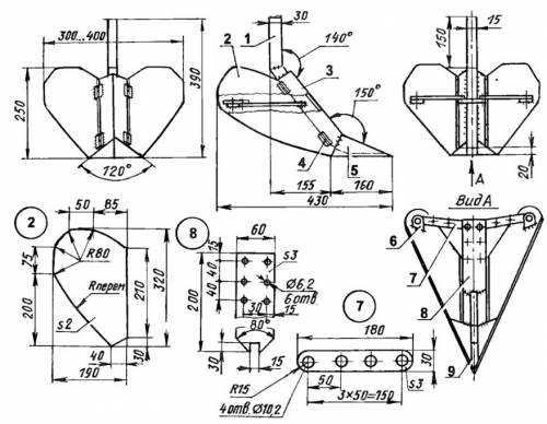 Fig 11. Drawing of a plow-type hiller
If you equip such an element with two rods: rear and front, it will be suitable for manual work. As an attachment, the plow can be attached to a bridge girder with an attachment point (to a moto- or electric cultivator).


