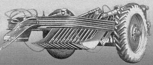
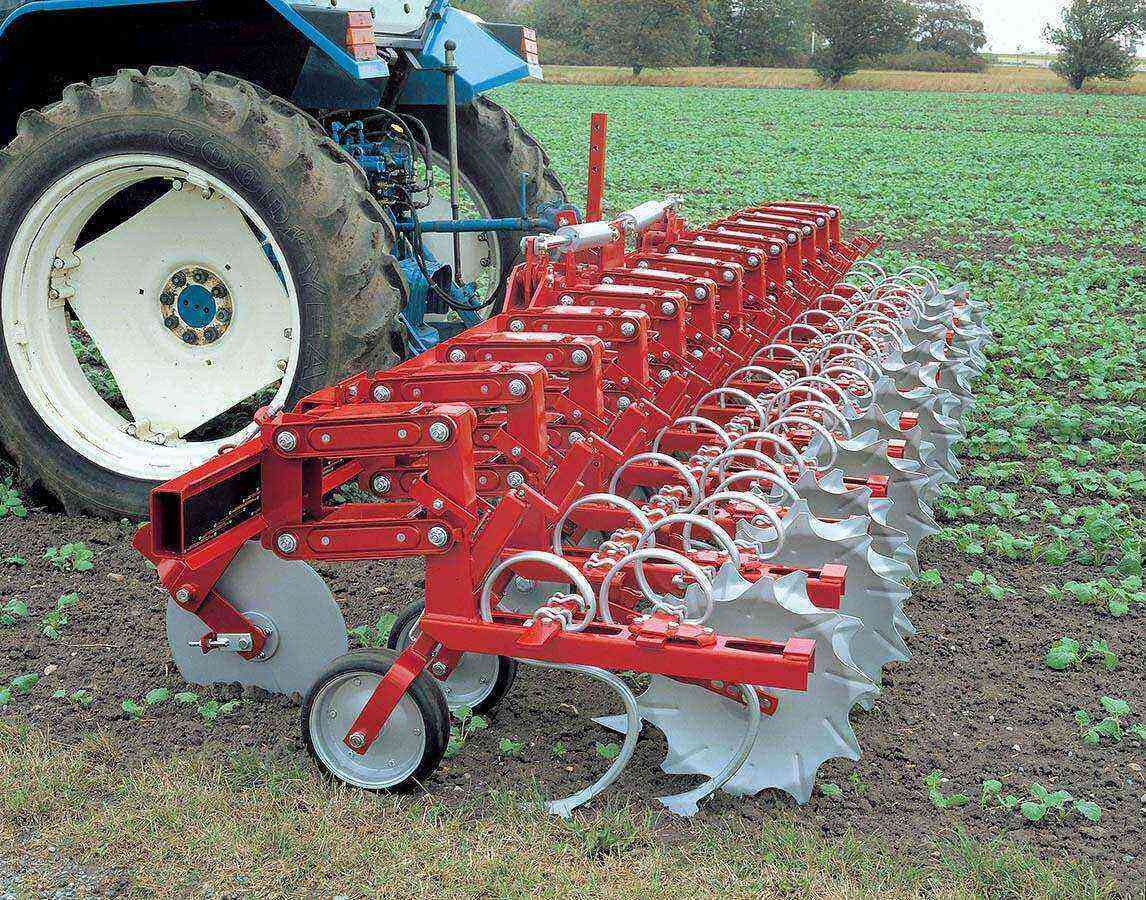
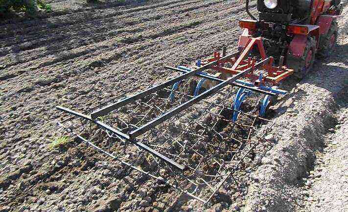
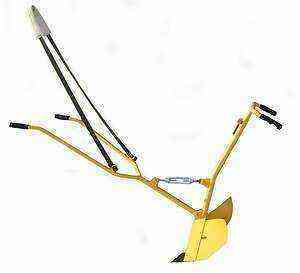
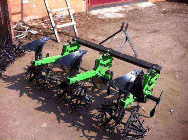
The first cultivation of the land is carried out 14-18 days after planting the tubers. Performing all the work manually is long and difficult. To facilitate and speed up the process, a potato cultivator is used – an agricultural soil cultivation machine. To expand the functions of equipment, additional or replaceable working elements (cutters, aerator, rake, hiller) are used. Cultivators appeared in the 18th century in England. Double-row and multi-row units were invented at the beginning of the 20th century. In the 30s of the last century, the technique was connected to a tractor.
Feasibility of use. As a result of the work of the units, the earth is loosened, large clods are broken, the soil is fluffed and leveled. As a result, the supply of oxygen to the roots of the potato bush increases, moisture is retained better. Particularly difficult, unprepared soils are loosened in several stages, layer by layer.
The use of a cultivator for processing potatoes helps to increase the yield by 2-3 times and speed up field work by 2-10 times. The agricultural machine is also used in preparing the soil for planting crops, when processing the soil in the fall, after harvesting. Most of all, heavy soddy-podzolic, clay and loamy soils need to be processed, less soils with a high sand content.
Types of cultivators for potatoes
1. To destination:
- steam cultivators – used for cultivating land prior to planting crops;
- row crops – used for loosening, weeding and hilling plants.
2. By the type of working tools:
- disc – capable of working soft soils and pruning weeds;
- with lancet paws – help to loosen the soil and apply fertilizers;
- plowshares – serve to prepare the soil for planting;
- milling – suitable for loosening dense soils;
- chisel – for deep soil cultivation.
3. By type of traction:
- gasoline (two-stroke and four-stroke) – capable of operating in remote areas, but requiring complex maintenance;
- electric – undemanding to care for, but need frequent battery charging or a connection to the power supply network;
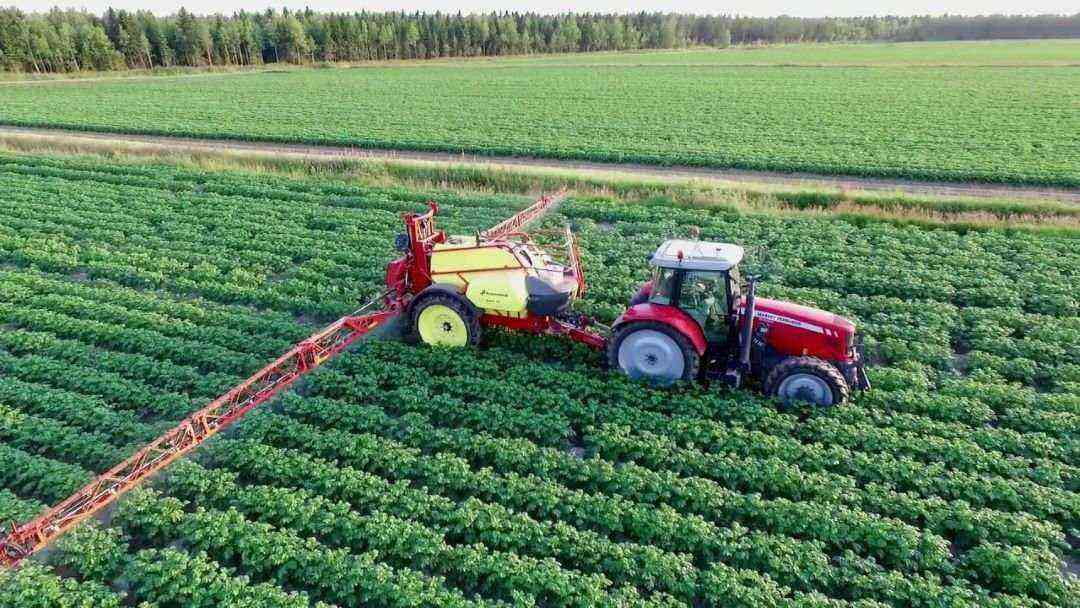
- mounted or trailed – attached to a tractor or walk-behind tractor;
- manual – simple, reliable, economical, but involve the use of physical force during work.
4. By power and weight:
- heavy – they differ with a capacity of up to 10 l / s and a mass of more than 60 kg, are used for large areas, with heavy soils, loosen the soil to a depth of 30-35 cm;
- medium – have a weight of up to 40 kg and a power of 4-6 l / s, go deeper into the ground by 20-25 cm;
- lungs – with a capacity of 2-3 l / s and weighing up to 20 kg, process the soil to a depth of 15 cm;
- ultralight – their capacity is 1-1,5 l / s and weight – up to 10 kg, capable of loosening the soil to a depth of 10 cm.
5. According to the number of rows to be hilled:
One of the most popular disc cultivator designs
Making a disc hand cultivator with your own hands
Making a hand cultivator is much cheaper than buying a factory one. In addition, it is more convenient to work with tools made from scrap materials: when designing, the master takes into account his height.
Features of the device. The disc cultivator is used to level the ground, break up large clods and cultivate the aisles: weeds are weeded and young shoots are healed.
The design features of such a device allow you to adjust the position of the working discs. When the wing nut rotates clockwise, the thrust moves up, the inner bracket raises the ends of the axles fixed in it, and the working discs change the angle of inclination. To return them to their original position, the wing nut is rotated in the opposite direction.
The list of tools for making a cultivator:
- welding machine and electrodes;
- gas cutter for metal – for cutting out parts from steel sheet;
- gas-burner;
- electric drill with drills for metal;
- device for cutting pipe threads;
- vice and a set of locksmith tools;
- grinder (angle grinder) – for cleaning welded seams.
Materials and components:
- metal sheet 4 mm thick, 1000 mm long, 500 mm wide;
- water and gas pipe (VGP) inch (33×2,5 mm), one segment 750 mm long, two – 250 mm each;
- ½ ”steel pipe (21,3×2,5 mm) – two sections 170 mm long;
- a solid cylinder with a diameter (D) 24 mm and a length (L) 250 mm, turned from a steel circle on a lathe, with a M16 threaded hole 50 mm deep;
- steel bar with a diameter of 16 mm, a length of 550 mm;
- steel bar with a diameter of 14 mm, a length of 550 mm;
- equal crosspiece with internal thread 1 inch – 1 pc .;
- gaika-baraшеek, M16 – 1 pc .;
- cotter pin 4×20, 4 pcs.
Assembly diagram of a manual disc cultivator
Disc – 4 pcs.; 2. Axle – 2 pcs .; 3. Bushing – 2 pcs .; 4. External bracket – 1 pc .; 5. Internal bracket – 1 pc .; 6. Stock – 1 piece; 7. Stand – 1 piece; 8. Handle – 2 pcs .; 9. Cross – 1 pc .; 10. Wing nut – 1 pc .; 11. Rod – 1 pc.
Production of parts
1. Working disk (pos. 1).
The most difficult part of making a manual potato cultivator is making working discs. If there is an opportunity to find ready-made (from some decommissioned agricultural machinery) – this is the best option. However, if there are no ready-made discs, you can make them yourself. It is necessary to cut 4 pieces with a diameter of 200 mm from a steel sheet with a thickness of 4 mm. Using a hammer with a semicircular head, forge concave discs from flat blanks. Drill a 22 mm hole in the center. To keep the edges sharp, they are sharpened with an abrasive wheel.
2. Axle for working discs (pos. 2).
A round steel pin with a diameter of 14 mm and a length of 550 mm is used to make an axis for the working discs. At a distance of 25 mm from the ends of the segment, through holes with a diameter of 5 mm are drilled on both sides – for cotter pins. You need to make 2 such axles.
3. Assembly unit for working disks.
Bushings under the disc axles (pos. 3). For their manufacture, use a ½ ”(21,3×2,5 mm) pipe section VDG, 170 mm long. Two working discs are put on each sleeve and welded symmetrically at a distance of 100 mm from each other. The bushings are packed with a thick lubricant.
4. Manufacturing of parts pos. 4 and pos. five.
The outer bracket (pos. 4) is cut out of a sheet with a thickness of at least 4 mm, a workpiece with a size of 1000×80 mm is cut out. A hole 34 mm in diameter is drilled in the center of the workpiece and bent 250 mm from each end of the strip at an angle of 90 °. It turns out a U-shaped bracket.
From a metal sheet with a thickness of at least 3-4 mm, a workpiece with a size of 290×60 mm is cut out for the inner bracket (pos. 3). Along the edges, retreating to the center by 15 mm, drill 2 holes with a diameter of 15 mm (under the axes of the discs, pos. 2). At a distance of 35 mm from the center on both sides (along the length), fold lines are drawn. The workpiece is bent along the outlined lines in the form of the letter “P”.
5. Making handles (pos. 8).
Take two pieces of an inch pipe 250 mm long and apply pipe threads to one end of each. On the other end, a ready-made rubber handle for tools is put on or wrapped with insulating tape.
6. Assembly of the welded structure:
- a rack (pos. 7) is inserted into the hole – a piece of VGP pipe with a diameter of DN 25 mm (33×2) 750 mm long. Weld to the bracket so that the pipe protrudes 50 mm downward. The rack is reinforced with two triangular struts made of sheet with a thickness of at least 4 mm.
- in the upper part of the rack, several turns of the external pipe thread 1 “are cut;
- to the inner bracket (item 5), a rod (item 6) is welded in the center, which is a carbon steel cylinder with a diameter of 24 mm and a length of 250 mm. A blind hole with a diameter of 16 mm and a depth of 50 mm must be drilled in it;
- thrust (pos. 11) – a steel rod with a diameter of 16 mm and a length of 550 mm, a metric M100 thread is applied to a section with a length of 16 mm. The rod is inserted into the hole in the rod (item 6) with the end without thread and welded to it with a continuous seam.
7. Installation of the rack and rod.
Before assembling the impellers on the outer and inner brackets (pos. 4 and pos. 5), mount the rack with the rod inside. Then they are fixed in a position where all the holes for fastening the wheel axles in the brackets are in a straight line. This can be done by inserting a 4 mm piece of bar into all 14 holes and adjusting the position of the rod and stand relative to each other.
The connecting piece between the stand (pos. 7) and the handles (pos. 8), as well as the rod position limiter, is the crosspiece (pos. 9).
Procedure:
- screw the upper end of the rack into one of the branch pipes of the cross and tighten the threaded connection;
- fix the traction in its original position by turning the wing nut along the thread protruding from the crosspiece clockwise until it stops, but without significant efforts;
- mount the cultivator handles: screw two handles (item 8) into the horizontal branch pipes of the cross.
8. Installation of working disks.
The assembled attachment points of the working discs (see item 3) are put on the axles (item 2). The ends of the axles are inserted into the holes in the outer (pos. 4) and inner brackets (pos. 5), then fixed with cotter pins.
head and editor-in-chief of the site. Hereditary gardener and agronomist
